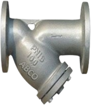
Y TYPE STRAINER
Technical Data:
| Manufacturing Std | Mfg. Std |
|---|---|
| Face to Face | DIN 3202 (Part -1) for size 200mm & Smaller ASME B16.10 for size 250mm & Larger |
| End Connection | Flanged Ends to ASME B16.5 RF / PN 40 |
| Inspection and Testing Std | BS 6755 (Part-1) |
| Category : | Uncategorized |
Description
Flanged and Grooved Type Y-Type Strainers
Size: 2” to 12”
Maximum Working Pressure: 300 PSI
Ductile Iron Construction (ASTM A536, 65-45-12)
Fusion Bonded Epoxy Coated
Removable cover for cleaning without removing strainer body from the pipeline
Strainer can be installed in either a horizontal or vertical position (Downward flow) with the screen element pointing downward
As the marketplace becomes increasingly competitive, more emphasis has been placed on reducing plant downtime and maintenance. In steam and condensate systems, damage to plant is frequently caused by pipeline debris such as scale, rust, jointing compound, weld metal and other solids, which may find their way into the pipeline system. Strainers are devices which arrest these solids in flowing liquids or gases, and protect equipment from their harmful effects, thus reducing downtime and maintenance. A strainer should be fitted upstream of every steam trap, flowmeter and control valve.
TESTING PRESSURE Kg / Sq.cm.
| TESTING | HYDRAULIC | |
|---|---|---|
| PN 16 | PN 40 | |
| BODY | 24 | 60 |
